TITLE: STATEMENT OF METHODOLOGY FOR INSTALLATION OF PERFORATED PIPE PURPOSE: The puprpose of this methodology is to illustrate the guidelines and procedures on the installation of Perforated Pipeping and underdrain works. SCOPE: The work procedure shall apply to Plumbing System for the Construction of all permanent and major temporary works. PROCEDURES: A. PRE-INSTALLATION 1. Secure the approved plans and drawings to be used for the activity 2. Verify if the area is ready for the activity 3. prepare all the materials needed based on the approved material submittals. Materials should be checked and inspected upon delivery prior to installation. 4. Prepare all the required manpower, tools and equipments, and PPE for the installation. 5. Secure all the required work permits and safety permits prior to exevution of activities. B. INSTALLATION PROCEDURE: 1. Drill holes in the PVC Pipe. The hole diameter shall be 13mm with spacing of 150mm staggered or as recommended by the designers an...

TITLE: METHOD STATEMENT FOR DETAILED PIPE WELDING
1. Purpose
This method statement describes in detail the welding process for piping system and the welder's qualification test procedures. This includes programs to maintain quality welding works.
2. Scope
This method statement outlines the method of welding process for pipe works and the welding procedure quallification test for welders. This method statement covers all pipe welding works at the project site and at the fabrication shop.
3. Testing Procedures
Inspection and Recording Requirements
a. The mechanical contractor will provide / submit to the Project / Contruction Manager up-to-date copies of "Welding Certificate" of welders to utilized at site prior to start of pipe welding works. Each qualified welder shall always carry with the a copy of their welding certificates for easy verification at site while they are doing welding activities.
b. The piping supervisor/foreman shall be fully familiar with the method statement / procedures for pipe welding works. He shall prepare the necessary reports to include inspection checklist, test plans and test resuts to demonstrate that these procedures and processes are strictly followed/implemented.
c. The QC Engineer in coordination with the welding supervisor/foreman shall verify the quality of the pipe welding works and its related testing in compliance to the project requirements and standards.
a. General
* Check all pipes and fittings to be joined/welded are free from defects, dents, deformities and are straight or not bent. Remove all defective pipes and fittings and replace with acceptable materials.
* Clean the pipes and fittings from foreign materials, dirts, oils (internal and external) before fitting up.
* For longer work breaks, place suitable stoppers / caps to prevent debris, dirts, and water from entering the pipes' open ends.
* Welding electrodes shall be stored as per manufacturer's instruction. Storage in welding rod oven is recommended to maintain dryness and right temperaature before usage.
b. Pipe Joint Preparation
* Cut the pipe to the required length using an appropriate pipe cutter or profile cutter (Oxy-Acetylene set), consider allowance for the for the pipe fitting. Works shall be carried out in accordance with the approved shop drawings and method statements.
* Check the pipes for straightness, and for squareness of the cut, or for correctness of angle of the cut as per approved shop drawings and site requirements.
c. Pipe to Pipe Fit-up
* Lay the two (2) pipes on top of the pipe stand or adjustable pipe support with each pipe ends aligned near each other by using adjustable bolt stopper (See illustration below).

Pipe to Pipe Fit-up
NOTES: For larger pipe sizes only, 4" diameter and above
*Bring the pipes together leaving a small welding gap approximately the diameter of a 2.4mm size of welding rod with its cover removed. Use adjustable bolt stoppers for easy and perfect alignment.
*After fit-up, remove the pipe stoppers. Grind flush all tack weld points, but make sure that there is no over grinding of the base metal.
*Place the spirit level on top of both pipe as shown in illustration above, the adjust the pipe/s using the pipe supports until both are leveled. Ensure that the two pipes outside surfaces are properly aligned and leveled.
*Tack weld at the top and bottom of the pipe joint.
*Repeat the same procedure to tack weld at the top and bottom of the pipe joint.
*Inspect the final pipe fit-up.
*Apply root pass welding.
*Inspect root pass welding quality.
*Apply succeeding welding process / capping.
*Remove the slags and spatter after welding by hammering and grinding. Check undercut and weld bead.
*The completed welding joint should be properly tagged using sticker indicating the welder's name and date.
*Schedule the pipe for testing as per testing requirements of the project specifications.
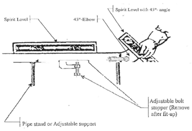
d. Forty Five (45 deg) Elbow to Pipe Fit-up
* Lay one (1) pipe on top of the pipe stand or adjustable pipe support.
* Level the pipe using spirit level.
* Place the 45 elbow to the end of the pipe leaving the required welding gap.
* Place a 45 spirit level on the face of the elbow until bubble is centered. Ensure that the two outside surfaces of the pipe and the elbow are aligned.
* Tack weld in place both the pipe and elbow and check the final fit-up.
* Apply root pass welding.
* Inspect root pass welding quality.
* Apply succeeding welding process / capping.
* Remove the slags and spatter after welding by hammering and grinding. Check undercut and weld bead.
* The completed welding joint should be properly tagged using sticker indicating the welder's name and date.
* Schedule the pipe for testing as per testing requirements of the project specifications.
e. Ninety (90) Elbow to Pipe Fit-up
* Lay one (1) pipe on top of the pipe stand or adjustable pipe support.
* Level the pipe using spirit level.
* Place the 90 elbow to the end of the pipe leaving the required welding gap.
* Place the 90 spirit level on the face of the elbow and make the necessary adjustments until the elbow is leveled. Ensure that the two outside surfaces of the pipe and the elbow are aligned.
* Tack weld in place both the pipe and elbow and check the final fit-up.
* Apply root pass welding.
* Inspect root pass welding quality.
* Apply succeeding welding process / capping.
* Remove the slags and spatter after welding by hammering and grinding. Check undercut and weld bead.
* The completed welding joint should be properly tagged using sticker indicating the welder's name and date.
* Schedule the pipe for testing as per testing requirements of the project specifications.

90 deg Elbow to Pipe Fit-up
f. Tee to Pipe Fit-up
* Lay one (1) pipe on top of the pipe stand or adjustable pipe support.* Level the pipe using spirit level.
* Place the Tee at the end of the pipe leaving the required welding gap.
* Place a spirit level on the face of the Tee and make the necessary adjustments until the elbow is leveled. Ensure that the two outside surfaces of the pipe and the elbow are aligned.
* Tack weld in place both the pipe and elbow and check the final fit-up.
* Apply root pass welding.
* Inspect root pass welding quality.
* Apply succeeding welding process / capping.
* Remove the slags and spatter after welding by hammering and grinding. Check undercut and weld bead.
* The completed welding joint should be properly tagged using sticker indicating the welder's name and date.
* Schedule the pipe for testing as per testing requirements of the project specifications.

Tee to Pipe Fit-up
f. Flange to Pipe Fit-up
* Lay one (1) pipe on top of the pipe stand or adjustable pipe support.
* Level the pipe using spirit level.
* Place the Flange at the end of the pipe leaving the required welding gap. If a slip-on flange is used, insert the pipe into the flange bore up to 5mm depth from the flange face to give enough space for a fillet weld.
* Place a spirit level on the face of the Flanged and make the necessary adjustments until the Flange is aligned and square with the pipe.
* Tack weld in place both the pipe and the flange and check the final fit-up.
* Apply root pass welding and / or fillet welding.
* Inspect root pass welding quality.
* Apply succeeding welding process / capping.
* Remove the slags and spatter after welding by hammering and grinding. Check undercut and weld bead.
* The completed welding joint should be properly tagged using sticker indicating the welder's name and date.
* Schedule the pipe for testing as per testing requirements of the project specifications.


Flange to Pipe Fit-up
4. Testing Material, Tools and Equipment
* Welding Machine
* Grinder & Pipe Cutter / Pipe Cutting Machine
* Threading Machine
* Blower
* Oxy-Acetylene Equipment
* Lifting Equipment (i.e. Chain Block & Wrench Puller)
* Hand tools
Comments
Post a Comment